Boolean Algebra
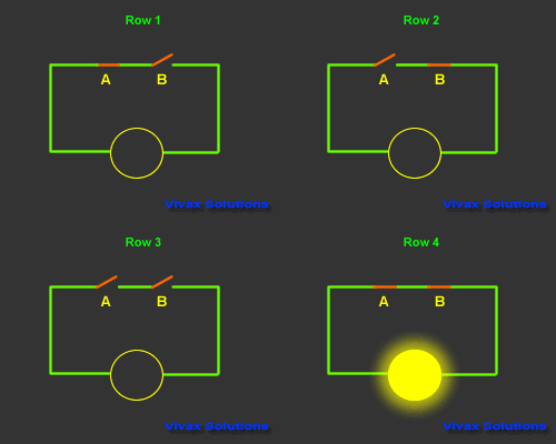
In the following circuit, a bulb is controlled by two switches.
This control mechanism is denoted as A.B - A and B - in Boolean Algebra. The state of the switch is
The output is considered as 1, when it is on and 0 when it is off. The way the bulb responds is considered as the
output and its state can also be described in terms of o -
off - and 1 - on.
On this basis, this animation can be summarized
in the table as follows:

| A | B | A.B | Output |
| 1 | 0 | 0 | 0 |
| 0 | 1 | 0 | 0 |
| 0 | 0 | 0 | 0 |
| 1 | 1 | 1 | 1 |
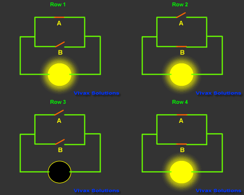
The following animation shows, the Boolean notation for the arrangement
of the switches is A + B - A or B.

The animation and the corresponding truth table explains how it works.
| A | B | A + B | Output |
| 1 | 0 | 1 | 1 |
| 0 | 1 | 1 | 1 |
| 0 | 0 | 0 | 0 |
| 1 | 1 | 1 | 1 |
The tables of this kind are called Truth Tables. A truth table describes how an arrangement of
switches controls the output of a logic circuit.
E.g.
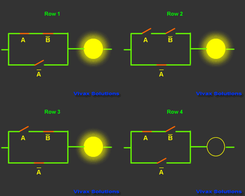
The animations and corresponding truth tables show
how Boolean algebra is interpreted in real world.

| A |
B |
B |
A |
Output |
| 1 |
0 |
1 |
0 |
1 |
| 0 |
1 |
0 |
1 |
1 |
| 0 |
0 |
1 |
1 |
1 |
| 1 |
1 |
0 |
0 |
0 |
B means the inverse of B; If B is 1, B
is 0 and vice versa.
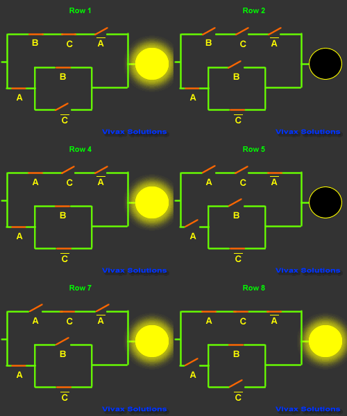
This is another truth table with its corresponding
circuit:

|
A |
B |
C |
A |
C |
Output |
| 1 |
1 |
1 |
0 |
0 |
1 |
| 1 |
0 |
0 |
0 |
1 |
0 |
| 1 |
0 |
1 |
0 |
0 |
0 |
| 1 |
1 |
0 |
0 |
1 |
1 |
| 0 |
0 |
0 |
1 |
1 |
0 |
| 0 |
1 |
0 |
1 |
1 |
0 |
| 1 |
0 |
1 |
0 |
1 |
1 |
| 0 |
1 |
1 |
1 |
0 |
1 |
Now try the following with a circuit and a
truth table:
- C.(A.B + A)
- A.C + A.B.C + A.B
- A.B.C.(A+B+C)
- A.(A.B.C + B.(A+C))
- C.(A+B).A