Kirchhoff's Laws
- At any junction in a circuit, the total sum of the currents coming in is equal to the total sum of those going out.
- The sum of EMF in a closed circuit, taken in a certain direction, is equal to the sum of IR in the same circuit.
E.g.1
Calculate the current through each resistor in the following circuit by using Kirchhoff's Laws.
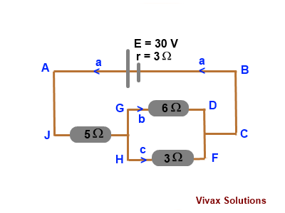
This problem can be solved by three different methods by using Kirchhoff's Laws:
Apply Kirchhoff's First Law to the Junction between G and H,
The current through 3Ω, c = a-b
Apply Kirchhoff's First Law to the junction between G and F,
The current at junction C = a
Method 1:
Now, let's apply Kirchhoff's Second Law to a set of different circuits:
Remember that the choice of direction dominates over everything:
For AJGDCBA:
30 = 3a + 5a + 6b
30 = 8a + 6b
8a + 6b = 30 <----1
For GHFDG:
0 = =3c -6b = 3(a-b) -6b - the EMF is zero in this circuit; direction of our choice overrules the direction of the existing currents
3a - 3b =6b
3a = 9b
a = 3b <----2
Substitute this in the equation 1,
30 = 8(3b) + 6b
30 = 30b
b = 1 A.
Substitute this in the equation 2,
a = 3 X 1 = 3
a = 3 A.
Therefore, the current through 3Ω = 2 A; the current through 6Ω = 1 A; the current through 5Ω = 3 A.
Method 2:
Apply Kirchhoff's First Law at Junction H:
Now, let's apply Kirchhoff's Second Law to the circuit:
Remember that the choice of direction dominates everything:
For AJGDCBA:
30 = 3a + 5a + 6b
30 = 8a + 6b
8a + 6b = 30 <----1
For AJHFCBA:
30 = 3(a-b) + 3a + 5a - direction of choice over-rules the direction of existing current
30 = 3a - 3b + 8a
11a -3b = 30<----2
2 X 2 => 22a - 6b = 60 <---3
1 + 2 => 30a = 90
a = 3 A.
Substitute this in the equation 1,
30 = 8 X 3 + 6b
6 = 6b
b = 1 A
Therefore, the current through 3Ω = 2 A; the current through 6Ω = 1 A; the current through 5Ω = 3 A.
Method 3:
Now, let's apply Kirchhoff's Second Law to another set of alternative circuits:
Remember that the choice of direction dominates over everything:
For AJHFCBA:
30 = 3a + 5a + 6b
30 = 8a + 6b <----1
For GHFDG:
0 = 3(a-b) -6b - the EMF is zero in this circuit; direction of our choice overrules the direction of the existing currents
3a - 3b =6b
3a = 9b
a = 3b <----2
Substitute this in the equation 1,
30 = 8(3b) + 6b
30 = 30b
b = 1 A.
Substitute this in the equation 2,
a = 3 X 1 = 3
a = 3 A.
Therefore, the current through 3Ω = 2 A; the current through 6Ω = 1 A; the current through 5Ω = 3 A.
The currents are the same the regardless of the circuit you choose as your choice.
E.g.2
Find the current through each resistor in the following circuit:
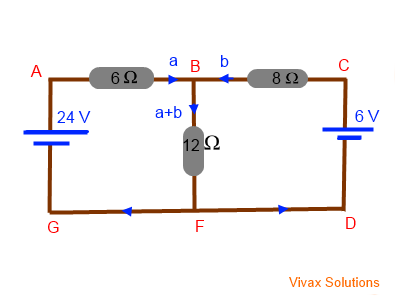
Apply Kirchhoff's First Law to the junction B:
The current through each branch is shown in the circuit diagram.
Now, let's apply Kirchhoff's Second Law to the circuits.
For ABFGA:
24 = 6a + 12(a+b) = 6a + 12a + 12b
24 = 18a + 12b <---1
For ABCDFGA
24 - 6 = 6a - 8b
18 = 6a - 8b <---2
3 X 2 => 54 = 18a -24b <---3
1 - 3 => -30 = 36b
b = -0.8A.
Negative sign means the current goes in the opposite direction.
From 1 => 24 = 18a + 12b
24 = 18a + 12(-5/6)
18a = 34
a = 17/9 = 1.8 A.
Therefore, the current through 6 Ω = 1.8 A; the current through 12 Ω = 1 A; the current through 8 Ω = 0.8 A.
How to maximize the power of a load
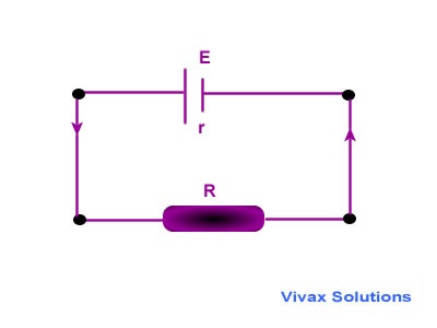
Total resistance = (R + r)
Current(I) = E / (R + r)
Power through the load(R) = VI = [E/(R + r)]2R
P = E2R/(R + r)2
Now, let's see how the power changes with different values of R.
Let E = 12V; r = 5Ω R changes from 0 to 10Ω
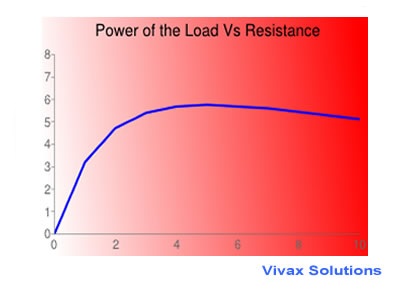
The graph shows that the power is maximum when R = r. So, in order to get the maximum power from a load, the resistance of the load must be equal to the internal resistance of the power source.
Proof:
P = E2R/(R + r)2
Let's differentiate P with respect to R
dP/dR = E2/ / (R + r)2 - 2E2R / (R + r)3
When P is maximum, dP/dR = 0
So, E2/ / (R + r)2 - 2E2R / (R + r)3 = 0
R + r = 2R
R = r
E.g.1
The EMF and the internal resistance of a cell are 6V and 2Ω respectively. Find the maximum power that can be obtained through an external load.
Since the internal resistance is 2 Ω, the resistance of the load must be 2 Ω as well, for maximum power.
Total resistance = 4 Ω
Total current = 6/4 = 1.5 A
V = IR = 1.5 X 2 = 3 V
P = VI = 1.5 X 3 = 4.5
P = 4.5 Watts.
E.g.2 What is resistance of the bulb, if it lights up with maximum brightness?
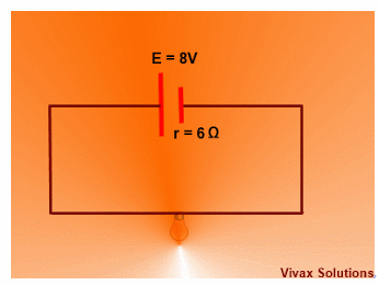
Ans:6 Ω
How to connect a voltmeter and an ammeter?
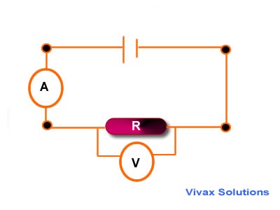
An ammeter is made in such a way that it has negligible resistance, because it is connected to a circuit in series. Since the ammeter should not alter the current in the circuit, it is made
with very little resistance in it. A voltmeter, on the other hand, is connected across two points in a circuit in parallel to find the potential difference between two points.
So, we must minimize the current through it. Otherwise, the voltage across the resistor could be influenced by the voltmeter. Therefore, a voltmeter is produced with a coil of very high resistance.
In theory, we assume the resistance of an ammeter as zero and that of a voltmeter as infinity, in our calculations.
Next
Previous