Parallel and Series Circuits
Master the fundamentals of A-Level Physics
With this comprehensive guide to series and parallel circuits, you can easily grasp a significant concept of electricity. Delve into the world of electricity as we explore the key concepts, calculations, and real-world applications of these circuit configurations.
From understanding voltage, current, and resistance to tackling complex circuit problems, this tutorial equips you with the essential knowledge to excel in your A-Level exams.
Whether you're a budding physicist or simply looking to enhance your scientific understanding, this resource provides clear explanations and practical examples to illuminate the intricacies of series and parallel circuits.
There is a fully interactive quiz for you to practise at the end of this tutorial.
Electrical devices can be connected in two different ways in a circuit.
- In series
- In parallel
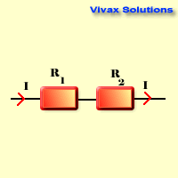
Series Circuits

Rtotal = R1 + R2
- The current is the same through each resistor.
- The voltage splits up.
- Total resistance exceeds the highest resistance of the resistors.
Proof
Consider two resistors, R1 and R2, connected in series.
1. Ohm's Law: V = IR
2. Total Voltage (Vt): Vt = V1 + V2
3. Substituting Ohm's Law: Vt = I x R1 + I x R2
4. Factoring out I: Vt = I * (R1 + I x R2)
Equivalent Resistance (Rt): Vt = I x Rt
6. Comparing Equations: Rt =R1 + R2
Therefore, the total resistance of resistors in series is equal to the sum of their individual resistances.
Parallel Circuits

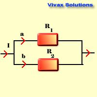
1/Rtotal = 1/R1 + 1/R2
- The voltage is the same through each resistor.
- The current splits up.
- Total resistance is less than the lowest resistance of the resistors
Proof of Total Resistance in Parallel Circuit
Let R1 and R2 be two resistors connected in parallel. The voltage across both resistors is the same (V).
I1 = V/R1
I2 = V/R2
It = I1 + I2
It = V/R1 + V/R2
It = V(1/R1 + 1/R2)
1/Rt = (1/R1 + 1/R2)<
Rt = 1 / (1/R1 + 1/R2)
Resistance Calculator
Move the sliders to change the resistance, calculate and then check the answers.
Worked Examples
E.g.1
A circuit contains a 9V battery, a 3Ω resistor, and a 6Ω resistor connected in series. Calculate the total resistance, the total current, and the voltage across each resistor.
Total resistance (Rₜ)
Rₜ = R₁ + R₂ = 3 + 6 = 9Ω
Total current (I):
I = V / Rₜ = 9 / 9 = 1A
Voltage across R₁ (V₁):
V₁ = I x R₁ = 1 x 3 = 3V
Voltage across R₂ (V₂):
V₂ = I x R₂ = 1 x 6 = 6V
E.g.2
A circuit contains a 12V battery, a 4Ω resistor, and an 8Ω resistor connected in parallel. Calculate the total resistance, the total current, and the current through each resistor.
Total resistance (Rₜ):
1/Rₜ = 1/R₁ + 1/R₂ = 1/4 + 1/8 = 3/8
Rₜ = 8/3 Ω ≈ 2.67Ω
Total current (I):
I = V / Rₜ = 12 / (8/3) = 4.5A
Current through R₁ (I₁):
I₁ = V / R₁ = 12 / 4 = 3A
Current through R₂ (I₂):
I₂ = V / R₂ = 12 / 8 = 1.5A
E.g.3
A circuit contains a 15V battery, a 2Ω resistor, a 4Ω resistor connected in series, and a 6Ω resistor connected in parallel with the 4Ω resistor. Calculate the total resistance, the total current, and the voltage across the 6Ω resistor.
Calculate the total resistance of the 4Ω and 6Ω resistors in parallel as well:
1/Rₚ = 1/4 + 1/6 = 5/12
Rₚ = 12/5 Ω = 2.4Ω
Calculate the total resistance of the circuit:
Rₜ = R₁ + Rₚ = 2 + 2.4 = 4.4Ω
Calculate the total current (I):
I = V / Rₜ = 15 / 4.4 ≈ 3.41A
Calculate the voltage across the 6Ω resistor:
Since the 4Ω and 6Ω resistors are in parallel, the voltage across both is the same.
V₆ = Vₚ = I x Rₚ = 3.41A x 2.4Ω ≈ 8.18V
E.g.4
A circuit contains a 24V battery, three resistors (R₁, R₂, and R₃) with values 5Ω, 8Ω, and 12Ω respectively. R₁ and R₂ are in series, and their combination is in parallel with R₃. Calculate the total resistance and the total current of the circuit, showing the steps of the solution.
Calculate the equivalent resistance of R₁ and R₂:
R₁₂ = R₁ + R₂ = 5 + 8 = 13Ω
Calculate the total resistance of the circuit:
1/Rₜ = 1/R₁₂ + 1/R₃ = 1/13 + 1/12
Rₜ ≈ 6.15Ω
Calculate the total current (I):
I = V / Rₜ = 24 / 6.15 ≈ 3.90A
E.g.5
A Christmas tree light string contains 50 identical bulbs, each with a resistance of 10Ω. The string is connected to a 120V power supply. Calculate the total resistance of the string and the current through each bulb.
Calculate the total resistance of the string:
Since the bulbs are connected in series, the total resistance is the sum of the individual resistances.
Rₜ = 50 x 10Ω = 500Ω
Calculate the total current (I):
I = V / Rₜ = 120 / 500 = 0.24A
Current through each bulb:
In a series circuit, the current is the same through all components.
Current through each bulb = 0.24A
A Quiz on Electric Circuits
Please answer the following questions.
- The dimensions of a solid iron cuboid are 6cm, 4cm and 2cm respectively. If the
resistivity of the substance is 0.002 units, find the resistance in the
following cases:
- If the current enters through the smallest
surface
- If the current enters through the largest
surface
- Explain the following:
- The copper cable of a lightning conductor
is very thick
- The wire inside a hair dryer is thin and
long
- The
resistance of a piece of wire is 9 Ohms. Find the new resistance, if it is
folded in two and then twisted.
- Can
Ohm’s law be applied to a light bulb which is hotter when in use, as the
physical conditions do not seem to be constant?
- You
are provided with three resistors of 12 Ohms each. How many different
combinations can be obtained from them? Calculate the total resistance in each
case.
- If two
resistors are connected in series the total resistance is 25 Ohms and if they
are connected in parallel the resistance is 6 Ohms. Find the resistance of
each.
- The
power of a light bulb is 60W at 240V. What is its new power if the voltage is
dropped down to 200V?
- Explain as to why the electricity is transmitted at a very high
voltage through thick copper cables through large distances.
- If a 2
kW kettle is used 2 hours a day for a period of one month, how many kWh are used
up?
- Explain the following:
- A switch is always connected across the
live wire
- TV does not need an earth wire
- Ammeters are connected in series whereas
voltmeters are connected in parallel
-
A circuit consists of five resistors connected as follows: R1 and R2 are in series, R3 is in parallel with the combination of R1 and R2, R4 is in series with R3, and finally, R5 is in parallel with the entire combination of R1, R2, R3, and R4. Given: R1 = 2Ω, R2 = 3Ω, R3 = 4Ω, R4 = 5Ω, and R5 = 6Ω. Find the total resistance of the circuit, showing each stage of your calculation in detail.
-
A Wheatstone bridge is a circuit used to measure unknown resistance. It consists of four resistors R1, R2, R3, and Rx (the unknown), in the form of the letter, Z . The bridge is balanced when the voltage difference between points B and D is zero. Given: R1 = 100Ω, R2 = 200Ω, R3 = 300Ω. If the bridge is balanced, find the value of Rx.
-
A circuit consists of a 12V battery, a 6Ω resistor, and two unknown resistors R1 and R2 connected in parallel. The total power dissipated in the circuit is 24W. If R1 is twice that of R2, find the values of R1 and R2, showing every step of your calculation.
-
A thermistor is a resistor whose resistance varies with temperature; the greater the temperature, the less the resistance. A thermistor with a resistance of 100Ω at 20°C is connected in series with a 900Ω resistor and a 12V battery. If the temperature increases to 30°C, the resistance of the thermistor decreases by 10%. Calculate the change in current through the circuit.
-
A circuit consists of three loops. Loop One contains a 12V battery and resistors R1 (4Ω) and R2 (6Ω). Loop Two contains a 9V battery and resistors R2 and R3 (8Ω). Loop Three contains resistors R3 and R4 (10Ω). Apply Kirchhoff's laws of electric circuits to find the current through each resistor.
-
A circuit consists of three identical resistors, each with resistance R. They are connected in a unique configuration: the first and second resistors are in series, and their combination is in parallel with the third resistor. A 12V battery is connected across the entire circuit. If the total power dissipated in the circuit is 24W, find the value of R.
-
A circuit contains a variable voltage source, a 5Ω resistor, and a 10Ω resistor connected in series. The voltage source is adjusted until the power dissipated in the 5Ω resistor is equal to the power dissipated in the 10Ω resistor. What is the voltage of the source at this point?
-
A non-linear resistor has a resistance that varies with the current flowing through it according to the equation R = 10 + 2I, where R is resistance in ohms and I is current in amperes. This resistor is connected in series with a 5Ω resistor and a 12V battery. Calculate the current in the circuit.
-
A circuit contains a 10Ω resistor, a 20Ω resistor, and a thermistor. The thermistor's resistance decreases linearly with temperature. At 20°C, its resistance is 30Ω. At 40°C, its resistance is 20Ω. The circuit is connected to a 12V battery. If the temperature increases from 20°C to 40°C, by what percentage does the total current in the circuit increase?
-
A circuit consists of five resistors connected as follows: R1, R2, and R3 are in series. Their combination is in parallel with R4. The combination of R1, R2, R3, and R4 is in series with R5. Given: R1 = 2Ω, R2 = 4Ω, R3 = 6Ω, R4 = 8Ω, and R5 = 10Ω. A 24V battery is connected across the entire circuit. Find the voltage drop across R3.